|
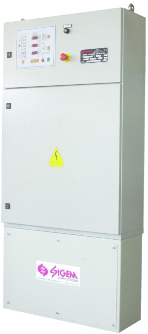
The Electric Control
panel, combined with an emergency Generator Set, allows the realization
of a system able to supply electric power within a few seconds of
Utility Mains failure. The enclosure is of steel sheet, accurately machined
and subject to a painting treatment using high resistance epoxy powder.
All electronic circuits for monitoring, control and signalling are
included in one single, compact microprocessor control card, flush
mounted on the Panel front door.
OPERATION
By means of key operated selector switch, the following modes can be
selected:
OFF/LOCKED: any operation excluded; engine start inhibition, with
forced control of load supply from the mains.
MANUAL: engine manual start and stop controls are enabled. The
Gen Set protection devices are activated. The starting control is
automatically disabled when the engine is running.
AUTOMATIC: automatic start upon mains failure, even on one single
phase, for min./max. voltage, or upon external consent. Starting is
obtained through a cycle of starting attempts, each followed by a pause.
In case of starting failure, the control panel gives an optical signal
and forces the Gen Set to shutdown, thus avoiding battery discharge.
Upon engine starting, the starter motor is automatically disconnected by
an electronic control device. Once the rated conditions are reached, the
Gen Set is connected to the load. The Gen Set is automatically
controlled by an appropriate protection device. When the mains returns
within the normal limits, the Gen Set is automatically disconnected from
the load. The load is then supplied by the mains and the engine is
stopped after an adjustable cooling time.
It is permited to TEST the automatic start for periodical testing
operations with safety protections enabled. Mains / Gen Set changeover is
disabled. Upon mains failure, the load is immediately supplied by the
Gen Set.
AUXILIARY SERVICES
The control panel includes:
-
Elettronic Automatic Battey Charger fed by
the Load Line
-
Single-phase voltage supply for engine
preheating
-
Acoustic alarm
-
Dedicated voltage-free contact (connected to
an internal board) for generating set failure
-
Programmable periodic automatic test, as
period and time required of the test itself
-
Motor driven-pump conrol circuit for the
automatic decanting from the external tank (optional)
CONTROLS
-
Engine start push-button
-
Engine stop push-button
-
Acoustic alarm silencing and programming and
reading display selection push button
-
Manual control for changeover switch
-
Emergency stop push-button
-
Reset push-button
DIGITAL MEASURING DEVICES
The Control Panel includes the following digital instruments:
-
Generator voltmeter: Phases L1/L2
L2/L3 L3/L1
-
Mains voltmeter: Phases L1/L2
L2/L3 L3/L1
-
Generator ammeter: Phases L1 L2 L3
-
Generator frequency meter
-
Gen Set hours counter
-
Battery voltmeter
-
Start-counter
OPTIONALS
-
Oil Pressure Gauge
-
Water thermometer
-
Revolution counter
-
Fuel level gauge
OPTICAL SIGNALLING AND GEN SET
PROTECTION
A set of light emitting diodes are used for signalling the current
status of the Generator Set and for the visualization of alarm
intervention.
STATUS
-
Mains live
-
Generator live
-
Mains contactor closed
-
Generator contactor closed
-
Engine running
ALARMS WITHOUT SHUT-DOWN
-
Fuel reserve
-
Maximum fuel level (for automatic topping up
systems from an external tank)
-
Battery failure
OPTIONALS
-
Pre-alarm for low oil pressure
-
Pre-alarm for high engine temperature
-
Pre-alarm for low radiator water level
ALARMS VISUALIZED ON DISPLAY
-
Over load
-
Generator under-voltage
-
Generator over-voltage
-
Generator under-frequency
-
Generator over-frequency
Other alarms are available (without
shut-down).
ALARMS WITH ENGINE SHUT-DOWN
-
Engine over crank
-
High engine temperature
-
Low oil pressure
-
Engine over speed
-
Generator overload
-
Fuel end
-
Low radiator water level (for water cooling
engine)
-
Emergency stop
An acoustic alarm is used for signalling
in case of defect. Signalling persists, even if the defect is cancelled,
until it is released (through RESET).
LIST OF THE MAIN SETTABLE PARAMETERS
The control card allows to set all the operating parameters.
Each parameter corresponds to a code number which identifies it and
allows its value to be set.
The main parameters are:
-
Mimimum mains 3-phases voltage
-
Threshold for generator voltage recognition
-
Gen Set connection delay
-
Mains return delay
-
Time delay for supply from Gen Set
-
Engine cooling delay
-
Start pulse duration
-
Shut-down pulse duration
-
Number of starting attempts
-
Generator under frequency threshold
-
Generator over frequency threshold
-
Generator under voltage threshold
-
Generator over voltage threshold
-
Generator periodical test start period
-
Generator periodical test duration
-
Over speed threshold
-
Changeover switching delay
-
Low oil pressure
-
Maximum mains voltage
-
Pause time between 2 starting trials
-
Frequency recognition starting engine
-
Current transformer ratio
Other parameters are available to
personalize the device, in relation to the various applications.
INTERFACE WITH TELECONTROL SYSTEM
(OPTIONAL)
The microprocessor control card is equipped with RS 232C for
possible connection to a local PC.
TECHNICAL FEATURES
-
Supply voltage: 230 / 400 Vac (other to be
specified)
-
Auxiliary voltage: 12 Vdc or 24 Vdc
-
Frequency: 50 Hz or 60 Hz
-
Insulation: > 50 Mohm
-
Dielectric strength AC: 2500V/1'
-
Dielectric strength DC: 1000V/1'
-
Level of protection: IP 40 (other protection
levels as optional)
-
Colour: RAL 7032
-
Ambient temperature min./max.: -10 /
+60° C
-
Conforming to: CEI - IEC - EN
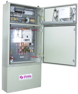
POWER CIRCUIT
The power circuit, when included, is separated from the auxiliary
control circuits, as per current safety regulations. In standard
configuration, with front door open, the level of mechanical protection
is equivalent to IP20.
Standard configuration includes:
-
4 poles Mains/Gen Set changeover
-
4 poles automatic circuit breaker
-
Differential device protection (optional).
When Mains/Gen Set changeover is external
to the control panel, dedicated voltage free contacts for changeover
control (connected to an internal terminal board) are supplied. |